What is a Coordinate system?
Contents
As we have studied in geometry, a coordinate system is a system that uses one or more numbers that determine the position. These numbers are Coordinate points. The order of the coordinates is significant, and they are sometimes identified by their position. They are in an order of tuples and sometimes by a letter, as in “the x-coordinate” or “the y-coordinate”. The coordinates are to be real numbers only. The use of a coordinate system is generally used in Geometrical, and mathematical modeling.
Need of the Cartesian coordinate system in CAD
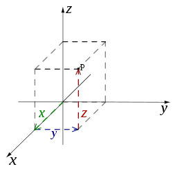
An example of a coordinate system is the Cartesian coordinate system. In the plane, two perpendicular lines are chosen and the coordinates of a point are taken to be the signed distances to the lines.
In three dimensions, three mutually orthogonal planes are there. The three coordinates of a point are the signed distances to each of the planes. Depending on the direction and order of the coordinate axes, the three-dimensional system may be right-handed or left-handed. This is one of many coordinate systems.
In CAD modeling knowledge of the Cartesian coordinate system is important. While working on wireframe modeling, or 3D Sketching we design the points and lines in these Cartesian coordinate systems.
The software uses these coordinate axis to give the Centre of mass, and position of the point or object. Solidworks has the option to create our Coordinate System in Solidworks. We have to give the reference axis and assign the custom axis and its direction. This helps in knowing the Centre of mass of the model or assembly of the newly created coordinate system. The coordinate system which we create is a local coordinate not a global coordinate.
Creating a Custom Coordinate System in Solidworks
Open the model or part in Solidworks. Now, Go to Features Tab > Reference > and then select Coordinate System.


In PropertyManager, Under Position, we have to select the vertex or the point where you want to create the system. You also have the option to create the coordinate system by giving numerical values.


In Orientation, we have to select the reference directions of the axis. We have 3 reference lines or edges namely the X-axis, the Y-axis, and the Z-axis. You can change the direction by Clicking on the Reverse direction option. We also have the option to change the orientation of the axis. For creating the coordinate system 2 edges or axis is sufficient to define the coordinate system. After defining the coordinate click on OK.


You can Rename the Coordinate System in the design tree. Right-Click on the Coordinate System in the design tree and then Click on Rename Tree Item. Now for this local coordinate system, you can get the center of mass about this coordinate. There are other things in which we can use a coordinate system. We can also set this Coordinate system as a global coordinate system while exporting the file. Go to Setting > Export > Output Coordinate system then, Click on OK.


