Home » Poka-Yoke for Welded and Machined-Part Assembly
Poka-Yoke for Welded and Machined-Part Assembly
Contents
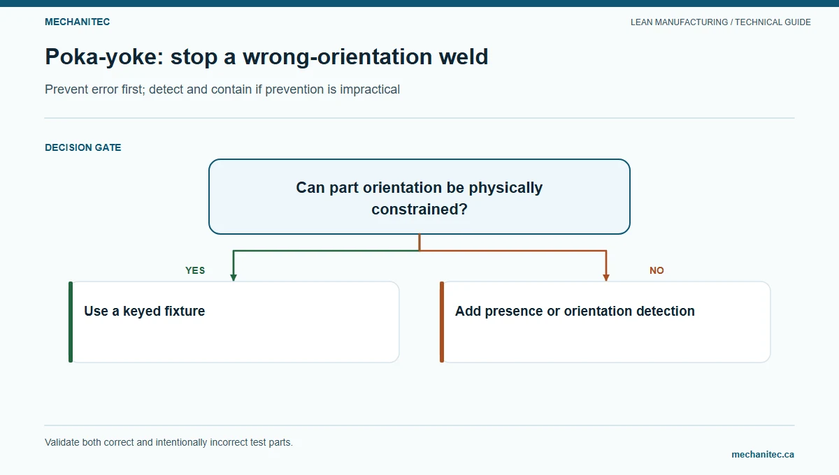
Poka-yoke, or error-proofing, uses a simple control to prevent a mistake or detect it before nonconforming work moves forward. Start with one documented defect mode, such as a bracket placed in the wrong orientation. The example below is fictional; it is a design and validation worksheet, not a real automotive supplier case or a substitute for engineering approval.
Prevent error first; detect and contain if prevention is impractical. Mechanitec instructional diagram.
Describe the defect before choosing a device
Separate the mistake from the resulting defect. Record the part and drawing revision, operation, intended condition, observed failure mode, where it was made, where it was detected, and how much affected work may be in scope. Contain suspect parts through the quality system. Use failure mode and effects analysis (FMEA) when appropriate to review severity, occurrence, and detection with the responsible team. Follow the site’s scoring rules; do not treat a generic risk-priority score as automatic approval.
Two similar brackets can be loaded with the weld flange reversed
Map part presentation and the exact orientation error at the fixture
Can the error be prevented by part geometry or a safe keyed location?
2. Trial device
Fixture accepts the approved orientation and makes the wrong orientation visibly detectable
Consider a qualified physical key or a verified presence/orientation sensor
Can the device damage a part, create a pinch hazard, or pass a wrong variant?
3. Verified work
Correct variant loads, is clamped, and proceeds under approved welding controls
Document inspection, maintenance, bypass control, and reaction to a failed check
Who verifies the control after setup, repair, or revision change?
The diagram describes a concept only. A qualified engineer must review fixture geometry, clamping, loading ergonomics, guarding, and the applicable welding procedure. Do not alter a qualified process or defeat an interlock to achieve a production target.
Define the critical feature and the escape point
Start with the feature that makes the orientation matter. A bracket may have a critical weld location, hole pattern, mating face, or clearance requirement. Record the part number and revision, the intended orientation, the operation where an error can enter, the next operation that could receive it, and the existing inspection point. State what counts as an escape: for example, a reversed bracket that passes the current check and reaches the next assembly operation. The exact definition must match the drawing and the site’s quality procedure.
Map the work sequence from part presentation through locating, clamping, welding, cooling, and inspection. Mark each opportunity to rotate the part, confuse a similar variant, skip a locator, or bypass a check. Use observed work and nonconformance records. If the team has only one reported defect, label the count and period; do not turn it into a stable defect rate. Record good parts that the current inspection rejects as well as defects it misses.
Review the risk with the people who design, weld, inspect, and maintain the process. FMEA can help organize failure modes, effects, causes, current controls, and actions. Follow the site’s approved method and escalation rules. A risk score prioritizes discussion; it does not replace required customer approval, process qualification, safety assessment, or containment.
Baseline record before designing a poka-yoke
Record
Example for a mirrored bracket
Why it matters
CTQ feature
Weld flange faces the specified side of the assembly
Connects the control to the approved drawing requirement
Error opportunity
Two mirrored brackets can be presented to the fixture
Identifies when prevention or detection must act
Existing control
Operator visual check before tack welding
Shows the current inspection point and its limits
Escape point
Reversed part can reach downstream assembly if missed
Defines the latest safe point to detect or contain
Baseline evidence
Defect count, inspected quantity, time period, revisions, and shifts
Prevents unsupported rates and mixed populations
Compare prevention and detection options
Countermeasure selection for a wrong-orientation defect mode
Option
How it helps
Failure mode to test
Distinct part geometry or keyed fixture
Can make an incorrect orientation physically unable to seat
Wear, damage, similar variants, forceful loading, and safe ergonomic access
Presence or orientation sensor
Can inhibit the next operation when the defined condition is absent
Can help workers identify the correct orientation before loading
Visibility, revision changes, lighting, and whether the cue is routinely followed
Inspection check
Can detect a defect at a defined point before downstream use
Inspection coverage, measurement method, human error, and escape to later work
Prefer prevention when the team can make the mistake impossible without adding risk or unreasonable effort. A warning or inspection control can still be useful, but it does not prove the defect cannot escape. Define how affected material is identified and controlled when a device fails.
Write the stop and release logic
For a mechanical key, define the locating surfaces and tolerances that allow the correct part to seat while preventing the reversed part from reaching the approved clamp position. Confirm that fixture wear, weld spatter, distortion, or an unauthorized shim cannot create a false fit. Check that the operator can load and remove the part without reaching through a hazard zone or forcing the work against the locator.
For a sensor, define the exact input that proves the correct part and orientation. A part-present switch may confirm presence but not orientation. A vision check may depend on lighting, surface condition, camera position, and software configuration. The control should prevent the next process step when the required condition is absent or uncertain, then give a clear fault indication and authorized recovery path. Do not rely on a green light unless the team has verified what signal causes it.
Specify who can reset the device and what evidence is required. The operator may clear a known obstruction only after the work is safe and the device returns to its defined normal state. Maintenance may repair a sensor; engineering or quality may need to approve a changed location or tolerance. If the control is bypassed for maintenance, identify affected parts and apply the approved alternate inspection until the control is restored. The bypass log should include start time, reason, authorization, scope, and verified return to service.
Stop and release rules for an orientation control
Condition
Required system response
Release evidence
Correct part and orientation confirmed
Allow the approved operation to continue
First-off check and required process record
Wrong orientation or missing part
Block the next process step and identify the cause
Correct loading confirmed by the defined check
Sensor or fixture fault
Stop affected work; contain parts since last verified good check
Repair, functional challenge, and authorized release
Unapproved bypass request
Do not bypass; use the site’s escalation and alternate-control process
Documented authorization and traceable inspection, if approved
Part revision or variant change
Hold setup until the approved control covers the new variant
Change review, challenge tests, and updated work instruction
Validate the control before release
Approve the design. Engineering, safety, quality, and production review the fixture or sensor against the controlled drawing and process requirements.
Define test conditions. List each approved part variant, correct orientation, representative wrong orientation, sensor-failure state, and any setup or revision condition.
Use controlled test pieces. Mark and segregate known-good and intentionally incorrect samples; never introduce an unmarked test part into production.
Record each response. For each trial, record the sample, expected response, actual response, device state, operator, date, and disposition.
Check false accepts and false rejects. A false accept is an incorrect condition allowed to proceed; a false reject is a correct condition blocked. Investigate both before release.
Set verification and maintenance. Define who checks the device at setup and after repair, what happens on failure, how bypass is controlled, and how the system restores normal operation.
Use an engineering-approved validation plan to determine the number of trials and acceptance criteria. A small demonstration sample is not proof of long-term reliability or a statistically valid escape rate. Continue monitoring actual defect and nuisance-stop records after release.
Work an illustrative 100-trial validation
Illustrative validation design — not observed production performance. Before installing a fixture key on a production cell, the team prepares known-good test pieces and safe, clearly identified challenge pieces. The challenge set includes the correct orientation, reversed orientation, and no-part condition. The test takes place outside production or under a controlled, approved validation plan so no deliberately incorrect piece can enter customer work.
For illustration, the team runs 100 challenges: 50 correctly oriented parts, 25 reversed parts, and 25 no-part conditions. The fixture allows 48 of the 50 correct parts to proceed and blocks 2 correct parts because a locator is misaligned. It blocks all 25 reversed parts and all 25 no-part conditions. In this designed sample, wrong-condition detection coverage is 50 ÷ 50 = 100%. The false-reject fraction for correct parts is 2 ÷ 50 = 4%. These values describe only this controlled test set. They do not establish a field escape rate or predict long-term reliability.
Illustrative challenge-test results for a keyed fixture
Challenge condition
Trials
Allowed to proceed
Blocked
Interpretation
Correct orientation
50
48
2
Two false rejects require investigation before release
Reversed orientation
25
0
25
All designed wrong-orientation challenges were blocked
No part / incomplete seat
25
0
25
All designed absence challenges were blocked
Total
100
48
52
Record each challenge and the expected and actual response
The two false rejects are not harmless. The team investigates whether the fixture key, part variation, burr, weld distortion, or loading method caused the failure. If it revises the key, it repeats the applicable challenge tests and documents the new configuration. Acceptance criteria must be approved before testing; do not redefine a failure as acceptable after seeing results. Any challenge piece stays identified and is accounted for after the test.
For a sensor-based control, add fault challenges such as disconnected input, dirty lens, lost communication, and power recovery where the design makes them relevant. Verify that uncertain or failed states stop the process safely, that the alarm identifies the condition, and that reset does not release an unverified part. An independent qualified reviewer should confirm the test plan for safety-related controls or critical characteristics.
Maintain the control after release
Put a functional check into setup or first-off standard work. The check should use an approved test piece or method, state the expected result, and be recorded. Define the interval based on risk, device behavior, maintenance needs, and process changes. Inspect the locating surfaces for wear or damage. For electronic controls, verify sensor alignment, wiring, configuration, and alarm response after a repair or program change.
Trend both defects and false stops. A low defect count can mean the control works, the process changed, or inspection stopped recording the condition. A high false-reject count can cause operators to ignore alarms or request bypasses. Review the actual records with production, quality, engineering, and maintenance. If a part revision, variant, material, fixture, weld procedure, or inspection method changes, route the update through formal change control and revalidate the affected conditions.
Illustrative rework-cost example
Assume a fictional shop finds 8 orientation errors in 400 inspected assemblies during a defined month. If each rework requires 12 minutes at a loaded labor rate of $42 per hour, the direct labor estimate is 8 × 12 ÷ 60 × $42 = $67.20. This excludes inspection, material, delay, customer impact, and device cost, so it is not the total cost of poor quality. Record actual local values before evaluating a countermeasure.
Check performance without hiding risk
Count defects by verified mode, operation, product revision, and detection point.
Track correct parts blocked by the control and incorrect conditions accepted by it.
Record downtime, bypass requests, maintenance, and false alerts.
Revalidate after a fixture change, sensor repair, software update, product revision, or process change.
Keep required inspection and customer controls unless the authorized quality system approves a documented change.
For quality at the source and process acceptance, see the Lean and quality guide. To give operators a defined escalation signal when a fixture or process is abnormal, see the Andon response guide.
Poka-yoke implementation checklist
Confirm the part, revision, CTQ, defect definition, and escape point.
Contain suspect product and establish the current defect and inspection baseline.
Map each orientation opportunity and identify prevention and detection options.
Review fixture geometry, process qualification, ergonomics, guarding, and failure modes with authorized owners.
Define normal, wrong-part, missing-part, fault, bypass, and revision-change responses.
Run and record approved challenge tests with identified test pieces; investigate false accepts and false rejects.
Assign setup verification, maintenance, monitoring, and revalidation owners before release.